この記事はまだ日本語で公開されていません。英語版を表示しています。
Bearing currents: how HF common-mode current destroys motor bearings
Bearings cause about half of all motor failures. In VFD-fed motors, HF common-mode current discharging through the bearings is a major reason why.
According to the IEEE Gold Book (IEEE Std 493), bearings account for about 51% of motor failures. In inverter-fed motors, a specific mechanism accelerates that wear.
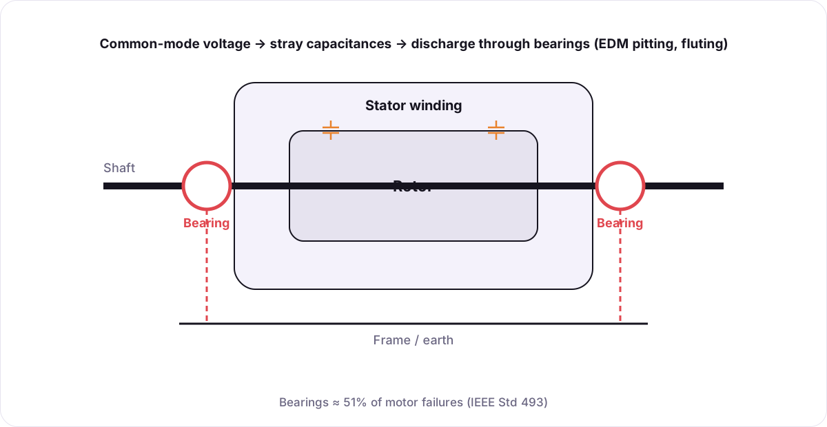 Common-mode voltage couples through stray capacitances, and the current discharges through the bearings to earth.
The mechanism
A PWM inverter's output is not a clean sine wave — its common-mode voltage switches with every edge. Stray capacitances between stator winding, rotor and frame let HF current flow. When the lubricating film in the bearing breaks down, that current discharges through the balls and races:
- EDM pitting — microscopic craters from each discharge
- Fluting — washboard-like grooves along the race, followed by noise, vibration and failure
Erdman et al. (1996) documented the effect of PWM inverters on bearing currents and shaft voltages; ABB's Technical Guide No. 5 describes mitigation in modern drive systems.
Mitigation layers
Common measures include proper grounding and bonding, insulated bearings, shaft-grounding rings and common-mode filtering at the drive output. The Denka® Platinum Plate contributes at the motor level: plates on the motor cables at the drive output absorb HF common-mode energy before it reaches the machine.