هذه المقالة غير متاحة بلغتك بعد. نعرض النسخة الإنجليزية.
Running a 5-step HF diagnostic: instruments and method
Spectrum analyser, RF current probe, IR camera and a Class A analyser: the exact method we use before and after a Denka® installation.
Every Denka® engagement follows the same five steps, aligned with IPMVP Option B/C and ASHRAE Guideline 14.
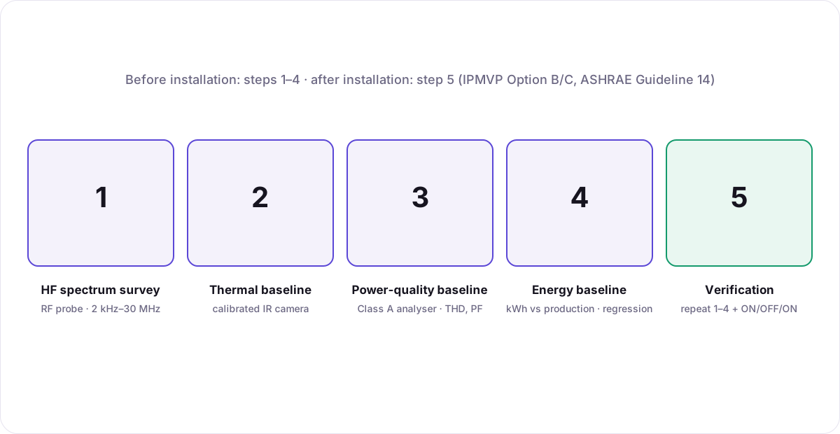 Baseline steps 1–4 before installation; step 5 repeats them afterwards.
Step 1 — HF noise spectrum survey
Clamp an RF current probe around the phase conductors and sweep 2 kHz – 30 MHz with a portable spectrum analyser (e.g. Rigol DSA815 or Tektronix RSA306B). Output: where HF noise is generated and where it flows.
Step 2 — Thermal baseline
Calibrated IR thermography of breaker output terminals, cables and motor terminal boxes.
Step 3 — Power-quality baseline
Log , and true power factor with a Class A analyser (e.g. Fluke 435-II, harmonics up to the 50th).
Step 4 — Energy baseline
Log active energy (kWh) and production (tons, m³, occupancy…) across a full operating cycle; build a multivariable regression baseline.
Step 5 — Post-installation verification
Repeat steps 1–4, plus an ON/OFF/ON (A-B-A) comparison under matched production.
Why a diagnostic before installation?
It decides plate placement and quantity, sets the agreed result for the 90-Day Result-Conditioned Money-Back Guarantee, and gives you the findings whether or not you proceed.