Este artículo aún no está disponible en su idioma. Se muestra la versión en inglés.
Why HF noise circulates inside your facility — and heats your own machines
Conducted emissions spread over low-impedance busbars into neighbouring machines, while the facility transformer largely keeps them in. That is why the heat shows up on the machine side.

Where does HF noise go once a drive or inverter injects it? Following the Denka® Scientific Whitepaper v3.0.0, the answer for most sites is: into your own equipment.
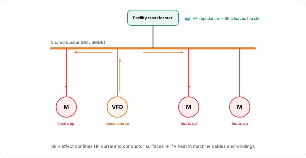 Noise injected by switching loads spreads over shared busbars and circulates into neighbouring machines; the facility transformer's high HF impedance limits what leaves the site.
1. Injection
VFDs, PV inverters, rectifiers and SMPS switch with steep edges, injecting differential- and common-mode current at 150 kHz – 30 MHz into their supply cables.
2. Spreading on shared busbars
At high frequency, DB and SMDB busbars are low-impedance paths. Noise from every source spreads across the shared distribution.
3. Circulation into neighbours
The HF current returns down other feeders into nearby motors, filter capacitors and equipment. The facility transformer's leakage impedance is high at MHz frequencies, so comparatively little leaves the site.
4. Heat on the machine side
Confined to the conductor surface by the skin effect ( mm at 150 kHz, 0.012 mm at 30 MHz), HF current meets high AC resistance, producing heat in machine cables and windings. Common-mode current also discharges through motor bearings to earth.
Sites without their own transformer can pass part of this noise to the utility — a separate case.
Placement follows physics
Denka® plates sit at the two positions in Whitepaper §5: breaker outputs feeding non-linear loads and drive output cables — absorbing HF energy close to where it is generated. Explore the interactive animation in the Technical Portal.